 home
home contact us
 about us
OEM Service
The OEM department specializes designing and manufacturing capacitors. We supply kinds of capacitors. Welcome to OEM services, please tell your demand, and we will feedback in 24 hours. Please contact us: ctcheam@camelcom.com.my.
Type of Film Capacitor:
General Information
1. Climatic category
The climatic category which the capacitor belongs to is expressed in three numbers separated by slashes, (IEC 60068-1: EXAMPLE 55/100/56).
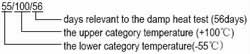
2. Upper category temperature
The highest environmental temperature determined by capacitor’s design and in which capacitor may continuously
work.
3. Lower category temperature
The lowest environmental temperature determined by capacitor’s design and in which capacitor may continuously work.
4. Rate voltage(UR)
The maximum D.C. voltage or peak value of pulse voltage that can be temperature between lower category temperature and rated temperature.
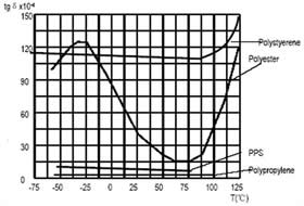
5. Dissipation factor (tgδ)
The dissipation factor is ratio between reactive power of the impedance of the capacitor and effective power when
capacitor is submitted to a sinusoidal voltage of specified frequency.
6. Self-healing (Only to metallized film capacitor)
The metal coatings of the metallized film , which are vacuum-deposited directly onto the plastic film, have a thickness of only several tens nanometer. At weak points or impurities in the dielectric, a dielectric breakdown would occur. The energy released by the arc discharge in the breakdown channel is sufficient to totally evaporate the thin metal coating in the vicinity of the channel. The insulated region thus resulting around the former faulty area will cause the capacitor to regain its full operation ability.
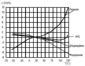
7. Temperature coefficient of capacitance (a)
The change rate of capacitance with temperature measured over a specified range of temperature. It is normally
expressed in parts per million per Celsius degree (10-6/°C) and referred to 20°C.
ai= (Ci-Co)/{Co(Ti-To)}
Ci: Capacitance at temperature Ti
Co: Capacitance at temperature To(20±2)°C
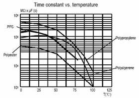
8. Insulation resistance (I.R)/Time Constant (t)
The insulation resistance is the ratio between an applied D.C. voltage and the resulting leakage current after a minute of charge. It is expressed in MΩ. In general, insulation resistance is used for describing smaller capacitance capacitors’ insulation character, Time constant for describing larger ones’ , for example: CR>0.33μF
The time constant is expressed in seconds with the following formula:
t[s]=I.R.[MΩ]xC[μF]
Caution Items In Using Plastic Film Capacitors
1. Operating voltage
The plastic film capacitor varies in the maximum applicable voltage depending on the applied voltage waveform, current waveform, frequency, ambient temperature (capacitor surface temperature), capacitance value, etc.. Be sure to use capacitors within the specified values by checking the voltage waveform, current waveform, and frequency applied to them (In the application of high frequency, the permissible voltage varies with the type of the capacitor. For detail, see the specification)
2. Operating current
The pulse (or AC) current flowing through the capacitor is expressed as : I=Cxdv/dt.
Due to the fact that dissipation factor of the capacitor will generate the internal heat under the application of high
frequency or high pulse current, temperature rise in it will occur and may cause deterioration of withstanding voltage, even lead to breakdown (smoking of firing). Therefore, the safety use of capacitor must be within the rated voltage (or category voltage) and the permissible current. The rated current must be considered by dividing into pulse current (peak current ) and continuous current (rms current) depending on the breakdown mode, and when using, make sure the both currents are within the permissible values.
3. Flame retardation
Although flame retardation epoxy resin and plastic case (UL94/V-0) is used in the coating or encapsulating of plastic film capacitor, continuous outran high temperature of flame will break the coating layer or plastic case of the capacitor, and may lead to melting or firing or the capacitor element.
4. Capacitor for electromagnetic interference suppression of AC power supply
When using a capacitor across-the-line as means for prevention of noise, not only the supply voltage is always applied, but also abnormal surge such as lighting is applied, which may lead to smoking of firing. Therefore, the across-the-line capacitor is strictly regulated in safety standard in each country.
5. Charging and discharging
Because the charging and discharging current of capacitor is obtained by the product of voltage rise rate (dv/dt) and capacitance, low voltage charging or discharging may also cause deterioration of capacitor such as shorting and open due to sudden charging and discharging current. When charging or discharging, pass though a resistance of 20 to 1000Ω/V or more to limit current.
When connecting multiple film capacitors in parallel in withstand voltage test or life test, connect a resistance of 20 to 100Ω/V or more in series to each capacitor. (For detail, see the specification).
6. When placing an order or inquiring sample please specify the following, as much as you can:
- Rated voltage: DC, AC.
- Capacitance value and capacitance tolerance: F, G, J, K, M.
- Finished product: color TV, monitor, switching power, lighting etc.
- Application or circuit diagram: DC circuit, AC pulse circuit(S-shaping correction, horizontal resonance circuit, peak absorption circuit), interference suppression circuit, high stability circuit etc.
- Condition of operation: pulse peak, frequency, waveform, current etc.
- Operating temperature.
- Dimensions: body, lead space, etc.
- Shape: enclosure (dip, box, etc), lead wire(straight, kinked, tapping etc)
- Safety: Influence to the other component when the capacitor gets short-circuited or open. Influence to the capacitor when the other component or the circuit works irregularly.
Typical Graphs
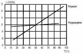
Capacitance change vs. temperature at 1KHz |
Dissipation factor vs. temperature at 1KHz |
 |
 |
Time constant vs. temperature |
Capacitance change vs. relative humidity (RH) |
 |
 |
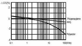
Capacitance change vs. frequency (RT) |
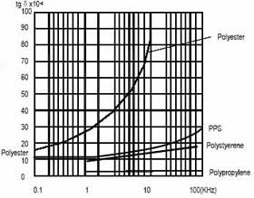
Dissipation change vs. frequency (RT) |
 |
 |
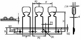
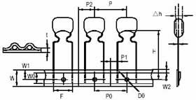
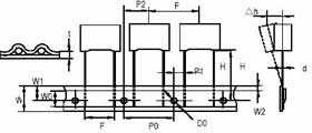
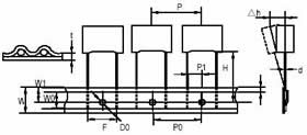
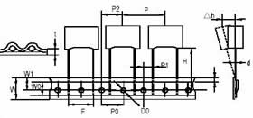
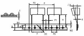
Lead Taping And Packaging Of Radial Ccomponents For Robot Insertion
 |
 |
 |
 |
 |
 |
| Description | Letter |
Dimension (mm) |
||||||
Fig.1 |
Fig.1/Fig.2 |
Fig.3 |
Fig.3 |
Fig.4 |
Fig.4 |
Tol. |
||
P=5mm |
P=7.5mm |
P=10mm |
P=15mm |
P=22.5mm |
P=27.5mm |
|||
| Lead wire diameter | d |
0.5/0.6 |
0.5/0.6 |
0.6 |
0.6/0.8 |
0.8 |
0.8 |
±0.05 |
| Tapping pitch | P |
12.7 |
12.7 |
25.4 |
25.4 |
38.1 |
38.1 |
±1 |
| Feed hole pitch | PO |
12.7 |
12.7 |
12.7 |
12.7 |
12.7 |
12.7 |
±0.2 |
| Centering of the lead wire | P1 |
3.85 |
2.6/3.75 |
7.7 |
5.2 |
7.8 |
5.3 |
±0.7 |
| Centering of the body | P2 |
6.35 |
6.35 |
12.7 |
12.7 |
19.05 |
19.05 |
±1.3 |
| Lead spacing (pitch) | F |
5 |
7.5 |
10 |
15 |
22.5 |
27.5 |
+0.6;-0.1 |
| Component alignment | D h |
0 |
0 |
0 |
0 |
0 |
0 |
±2 |
| Height of component from tape center | H |
18.5 |
18.5 |
18.5 |
18.5 |
18.5 |
18.5 |
±0.5 |
| Carrier tape width | W |
18 |
18 |
18 |
18 |
18 |
18 |
+1;-0.5 |
| Hold down tape width | WO |
6 |
6 |
9 |
10 |
10 |
10 |
min |
| Hole position | W1 |
9 |
9 |
9 |
9 |
9 |
9 |
±0.5 |
| Hold down tape position | W2 |
3 |
3 |
3 |
3 |
3 |
3 |
max |
| Feed hole diameter | Do |
4 |
4 |
4 |
4 |
4 |
4 |
±0.2 |
| Tape thickness | t |
0.7 |
0.7 |
0.7 |
0.7 |
0.7 |
0.7 |
±0.2 |
* Allowance of accumulated pitch less than 1mm at the sum of 20 pitches.
* Continuous empty component less than 3pcs.
* Total empty on one reel less than 1%.
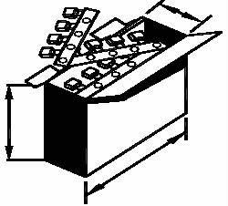
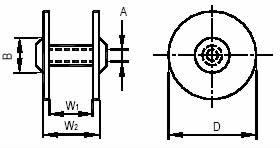
Packing Specifications
| Packing type |
|
 |
||
Dimensions Unit : mm |
A |
14~30 |
A |
50 +5;-2 |
B |
80 min |
B |
260±2 |
|
D |
370 max |
C |
330±2 |
|
W1 |
45 +5;-2 |
- |
- |
|
W2 |
55 max |
- |
- |
|
| Packing qty per ree/box | C≦0.022 1500pcs |
C>0.022 1000pcs |
C≦0.047 1500pcs |
C>0.047 1000pcs |
EIA STANDARD RS-296-D
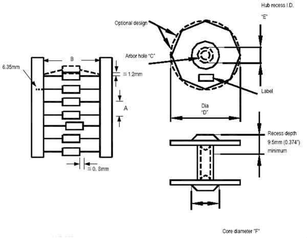
1. Reel label consists of:
2. Component type
3. Electrical values
4. Manufacturer’s name
5. Date
6. Component quantity
CAPACITOR BODY DIAMETER |
CAPACITOR PITCH”A”±0.5mm (0.020”) |
≧5mm (≧ 0.197”) |
5mm or 0.200” |
5.01~10mm (0.197~0.394”) |
10mm or 0.400” |
10.01~15mm (0.394~0.591”) |
15mm or 0.600” |
| CAPACITOR BODY LENGTH | INSIDE TAPE SPACING “B” ±1.5mm (0.059”) |
| ≧16.50mm (≧0.65”) | 52.44mm or 2.062” |
| 16.51~28.45mm (0.651~1.12”) | 63.5mm or 2.500” |
| 28.46~37.00mm (1.121~1.45”) | 76.0mm or 2.874” |
| EIA Std. RF Spec |
C |
D |
E |
F |
13.9~38.1mm (0.54~1.50”) |
76.2~355.6mm (3.0~14.0”) |
28.6~78.0mm (1.126~3.071”) |
34.5~92.0mm (1.374’3.626”) |
|
14.5mm (0.570”) |
381.0mm (15”) |
54.2mm (2.130”) |
61.0mm (2.401”) |
CAPACITOR BODY DIA. |
PITCH |
QUANTITY PCS/REEL |
≧ 5.0mm |
6 mm |
4000 max |
5.1~7.0mm |
10 mm |
2000 max |
7.1~9.5mm |
10 mm |
1000 max |
Plastic Film Capacitors Part Number System
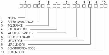
1. Series
PEI |
PES |
PEN |
MPE |
MES |
MEM |
MMB |
MEB |
MET |
MEF |
PPL |
PPN |
PPT |
MPP |
MPB |
MPT |
MPF |
MPS |
MSB |
PST |
PSC |
PPS |
PSM |
PSB |
PSH |
PHB |
MPX |
MX1 |
MPY |
SKC |
PSA |
PSR |
PCC |
PAC |
- |
- |
2. Rated Capacitance
| Code | 101 |
102 |
103 |
104 |
105 |
106 |
| PF | 100PF |
1000PF |
10000PF |
100000NF |
1000000NF |
10000000NF |
| NF | - |
1NF |
10NF |
100NF |
1000NF |
10000NF |
| µF | - |
0.001µF |
0.01µF |
0.1µF |
1.0µF |
10µF |
3. Tolerance
| Tolerance | ±1% |
±2% |
±2.5% |
±3% |
±5% |
±10% |
±20% |
| Symbols | F |
G |
H |
I |
J |
K |
M |
4. Rated Voltage
| No | A | B | C | D | E | F | G | H | I | J | K | L | M | N | O | P |
| 0 | 1.0 | 1.25 | 1.6 | 2.0 | 2.5 | 3.15 | 4.0 | 5.0 | - | 6.3 | 8.0 | - | - | - | - | - |
| 1 | 10 | 12.5 | 16 | 20 | 25 | 31.5 | 40 | 50 | - | 63 | 80 | - | - | - | - | - |
| 2 | 100 | 125 | 160 | 200 | 250 | 315 | 400 | 500 | - | 630 | 800 | - | - | - | - | - |
| 3 | 1000 | 1250 | 1600 | 2000 | 2500 | 3150 | 4000 | 5000 | - | 6300 | 8000 | - | - | - | - | - |
| 4 | 10000 | 12500 | 16000 | 20000 | 25000 | 31500 | 40000 | 50000 | - | 63000 | 80000 | - | - | - | - | - |
| 5 | 125 VAC | 225 VAC | 325VAC | 425 VAC | 525 VAC | 625 VAC | 725 VAC | 825 VAC | 925VAC | 1025 VAC | 1125 VAC | 1225 VAC | - | - | - | - |
| 6 | 150 VAC | 250 VAC | 350VAC | 450 VAC | 550 VAC | 650 VAC | 750 VAC | 850 VAC | 950VAC | 1050 VAC | 1150 VAC | 1250 VAC | - | - | - | - |
| 7 | 175 VAC | 275 VAC | 375VAC | 475 VAC | 575 VAC | 675 VAC | 775 VAC | 875 VAC | 975VAC | 1075 VAC | 1175 VAC | 1275 VAC | - | - | - | - |
| 8 | 200 VAC | 300 VAC | 400VAC | 500 VAC | 600 VAC | 700 VAC | 800 VAC | 900 VAC | 1000VAC | 1100 VAC | 1200 VAC | 1300 VAC | - | - | - | - |
5. Width or Diameter mm
No |
0 |
1 |
2 |
3 |
4 |
5 |
6 |
7 |
8 |
9 |
- |
- |
1 |
2.5 |
3 |
4 |
5 |
6 |
7.5 |
8 |
9 |
A |
10 |
11 |
12.5 |
13 |
14 |
15 |
16 |
17.5 |
18 |
19 |
B |
20 |
21 |
22.5 |
23 |
24 |
25 |
26 |
27.5 |
28 |
29 |
C |
30 |
31 |
32.5 |
33 |
34 |
35 |
36 |
37.5 |
38 |
39 |
D |
40 |
41 |
42.5 |
43 |
44 |
45 |
46 |
47.5 |
48 |
49 |
E |
50 |
51 |
52.5 |
53 |
54 |
55 |
56 |
57.5 |
58 |
59 |
F |
60 |
61 |
62.5 |
63 |
64 |
65 |
66 |
67.5 |
68 |
69 |
G |
70 |
71 |
72.5 |
73 |
74 |
75 |
76 |
77.5 |
78 |
79 |
H |
80 |
81 |
82.5 |
83 |
84 |
85 |
86 |
87.5 |
88 |
89 |
I |
90 |
91 |
92.5 |
93 |
94 |
95 |
96 |
97.5 |
98 |
99 |
J |
100 |
101 |
102.5 |
103 |
104 |
105 |
106 |
107.5 |
108 |
109 |
K |
110 |
111 |
112.5 |
113 |
114 |
115 |
116 |
117.5 |
118 |
119 |
L |
120 |
121 |
122.5 |
123 |
124 |
125 |
126 |
127.5 |
128 |
129 |
M |
130 |
131 |
132.5 |
133 |
134 |
135 |
136 |
137.5 |
138 |
139 |
N |
140 |
141 |
142.5 |
143 |
144 |
145 |
146 |
147.5 |
148 |
149 |
O |
150 |
151 |
152.5 |
153 |
154 |
155 |
156 |
157.5 |
158 |
159 |
P |
160 |
161 |
162.5 |
163 |
164 |
165 |
166 |
167.5 |
168 |
169 |
Q |
170 |
171 |
172.5 |
173 |
174 |
175 |
176 |
177.5 |
178 |
179 |
R |
180 |
181 |
182.5 |
183 |
184 |
185 |
186 |
187.5 |
188 |
189 |
S |
190 |
191 |
192.5 |
193 |
194 |
195 |
196 |
197.5 |
198 |
199 |
T |
200 |
201 |
202.5 |
203 |
204 |
205 |
206 |
207.5 |
208 |
209 |
U |
210 |
211 |
212.5 |
213 |
214 |
215 |
216 |
217.5 |
218 |
219 |
V |
220 |
221 |
222.5 |
223 |
224 |
225 |
226 |
227.5 |
228 |
229 |
W |
230 |
231 |
232.5 |
233 |
234 |
235 |
236 |
237.5 |
238 |
239 |
X |
240 |
241 |
242.5 |
243 |
244 |
245 |
246 |
247.5 |
248 |
249 |
Y |
250 |
251 |
252.5 |
253 |
254 |
255 |
256 |
257.5 |
258 |
259 |
Z |
260 |
261 |
262.5 |
263 |
264 |
265 |
266 |
267.5 |
268 |
269 |
6. Pitch or Length mm
No |
0 |
1 |
2 |
3 |
4 |
5 |
6 |
7 |
8 |
9 |
- |
- |
1 |
2.5 |
3 |
4 |
5 |
6 |
7.5 |
8 |
9 |
A |
10 |
11 |
12.5 |
13 |
14 |
15 |
16 |
17.5 |
18 |
19 |
B |
20 |
21 |
22.5 |
23 |
24 |
25 |
26 |
27.5 |
28 |
29 |
C |
30 |
31 |
32.5 |
33 |
34 |
35 |
36 |
37.5 |
38 |
39 |
D |
40 |
41 |
42.5 |
43 |
44 |
45 |
46 |
47.5 |
48 |
49 |
E |
50 |
51 |
52.5 |
53 |
54 |
55 |
56 |
57.5 |
58 |
59 |
F |
60 |
61 |
62.5 |
63 |
64 |
65 |
66 |
67.5 |
68 |
69 |
G |
70 |
71 |
72.5 |
73 |
74 |
75 |
76 |
77.5 |
78 |
79 |
H |
80 |
81 |
82.5 |
83 |
84 |
85 |
86 |
87.5 |
88 |
89 |
I |
90 |
91 |
92.5 |
93 |
94 |
95 |
96 |
97.5 |
98 |
99 |
J |
100 |
101 |
102.5 |
103 |
104 |
105 |
106 |
107.5 |
108 |
109 |
K |
110 |
111 |
112.5 |
113 |
114 |
115 |
116 |
117.5 |
118 |
119 |
L |
120 |
121 |
122.5 |
123 |
124 |
125 |
126 |
127.5 |
128 |
129 |
M |
130 |
131 |
132.5 |
133 |
134 |
135 |
136 |
137.5 |
138 |
139 |
N |
140 |
141 |
142.5 |
143 |
144 |
145 |
146 |
147.5 |
148 |
149 |
O |
150 |
151 |
152.5 |
153 |
154 |
155 |
156 |
157.5 |
158 |
159 |
P |
160 |
161 |
162.5 |
163 |
164 |
165 |
166 |
167.5 |
168 |
169 |
Q |
170 |
171 |
172.5 |
173 |
174 |
175 |
176 |
177.5 |
178 |
179 |
R |
180 |
181 |
182.5 |
183 |
184 |
185 |
186 |
187.5 |
188 |
189 |
S |
190 |
191 |
192.5 |
193 |
194 |
195 |
196 |
197.5 |
198 |
199 |
T |
200 |
201 |
202.5 |
203 |
204 |
205 |
206 |
207.5 |
208 |
209 |
U |
210 |
211 |
212.5 |
213 |
214 |
215 |
216 |
217.5 |
218 |
219 |
V |
220 |
221 |
222.5 |
223 |
224 |
225 |
226 |
227.5 |
228 |
229 |
W |
230 |
231 |
232.5 |
233 |
234 |
235 |
236 |
237.5 |
238 |
239 |
X |
240 |
241 |
242.5 |
243 |
244 |
245 |
246 |
247.5 |
248 |
249 |
Y |
250 |
251 |
252.5 |
253 |
254 |
255 |
256 |
257.5 |
258 |
259 |
Z |
260 |
261 |
262.5 |
263 |
264 |
265 |
266 |
267.5 |
268 |
269 |
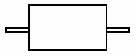
7. Lead Style
| Wire Shape | ||||
| Code | Forming Style | RADIAL | AXIAL | |
0 |
No forming | 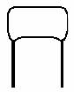 |
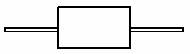 |
|
1 |
KINK Strait forming | 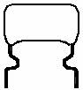 |
||
2 |
Outward kink | Flat kink |  |
 |
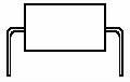
3 |
Inward kink | Stand kink |  |
 |
4 |
Strait cut short lead |  |
 |
|
5 |
KINK Forming and cut short lead | 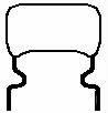 |
||
6 |
Outward forming short lead | Flat forming short lead | 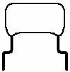 |
 |
7 |
Inward kink short lead | Stand form short lead |  |
|
8 |
Double kink short lead |  |
 |
|
8. Lead Length mm
Code |
T |
0 |
1 |
2 |
3 |
4 |
5 |
6 |
7 |
8 |
9 |
Meaning |
Tapping |
3.5 |
3.8±0.3 |
4±0.5 |
4.5 |
5±0.5 |
5±1 |
6 |
7 |
8 |
9 |
Code |
A |
B |
C |
D |
E |
F |
G |
H |
J |
K |
L |
Meaning |
10 |
11 |
12 |
13 |
14 |
15 |
16 |
17 |
18 |
19 |
20 |
Code |
M |
N |
P |
Q |
R |
S |
U |
V |
W |
X |
Y |
Meaning |
21 |
22 |
23 |
24 |
25 |
30 |
35 |
40 |
45 |
50 |
55 |
Code |
Z
|
Meaning |
>60 |
9. Construction Code (internal use)
10. Design Code
There is only two digit for design code, it means that after the segregation of the front 16 digit, we are still get an
similar design so we must use design code to do the final distinguish to prevent mistake. This design code should only publish by an engineer from the headquarter. Please be noted that digit 10 to 13 is not for segregation use, this means if those 4 digits different, maybe they are exactly the same parts. You will not be able to see the design code from capacitors body.
Date Code
YEARS |
YEARS |
MONTH marked by the side of the capacitance |
MONTH marked by the side of the capacitance |
||||
2004 |
C + |
2010 |
C∣ |
1 |
104a |
7 |
104n |
2005 |
+C |
2011 |
- C |
2 |
104b |
8 |
104v |
2006 |
C+ |
2012 |
C · |
3 |
104c |
9 |
104p |
2007 |
+ C |
2013 |
. C |
4 |
105d |
10 |
104s |
2008 |
C - |
2014 |
. C |
5 |
104e |
11 |
104t |
2009 |
∣C |
2015 |
C . |
6 |
104h |
12 |
104r |