 home
home contact us
 about us
OEM Service
The OEM department specializes designing and manufacturing capacitors. We supply kinds of capacitors. Welcome to OEM services, please tell your demand, and we will feedback in 24 hours. Please contact us: ctcheam@camelcom.com.my.
Type of Tantalum Capacitor:
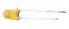
| A. TCS Tantalum electrolytic capacitors surface mount type |
 |
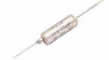
| B. TCD Tantalum electrolytic capacitors resin dipped |
 |
| C. TCA Metal case tantalum capacitors |
 |
General Information
1. Direct DC voltage
The rated voltage(UR), indicated on the capacitor, is the maximum DC voltage which can be applied continuously between -55°C and +85°C
2. Reverse voltage
This characteristic is not guaranteed for all types.
Maximum reverse voltage is generally:
0.15 times UR at +20°C
0.05 times UR at +85°C
0.01 times UR a t +125°C
Tests are performed with the following conditions:
125 hours under reverse voltage followed by 125 hours under direct voltage.
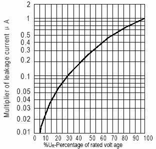
3. Leakage current
Leakage current is the residual current which flows through the capacitor after the charging time, under rated voltage. It is measured after a time not exceeding 5 minutes and is given in µA.
It is equivalent to the insulation resistance to the capacitor and it must be as low as possible.
Maximum leakage current is a function of capacitance and rated voltage values and is given, for each type, in the data sheets.
At 20°C, THE LIMIT IS GENERALLY:
If max (µA)=0.01xCRxUR
With CR in µF and UR in V.
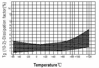
4. Dissipation factor
Dissipation factor is generally measured at the same time as the capacitance, with the same conditions. It is a
function of the series resistance of the capacitor and the capacitance at low frequency.
DF=ESR x C x 2πf
At low frequency, the series resistance is the sum of an ohm part (leads, contacts, MnO2..) and the dielectric losses. Dissipation factor is given in % and maximum limits are given for each type in the data sheets.
5. Equivalent series resistance or impedance
Equivalent circuit of a capacitor
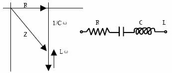
R: equivalent series resistance of the capacitor (leads, contacts, MnO2, dielectric losses)
L: inductance mainly due to the leads
C: capacitance
Equivalent Series Resistance for TCA types
For these types which are specially designed to e used in power supplies and converters, a maximum ESR is given at a frequency of 100kHz or 500kHz. Parameters such output ripple voltage and ripple current capability are directly a function of the ESR value.
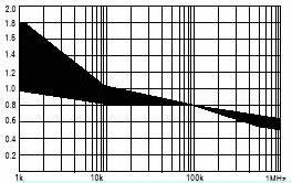
Impedance (for standard products)
For the others types, a maximum limit is given for the impedance.
The formula for impedance is:
Z=√(R2+(Lω-1/Cω)2)
Examples of impedance curves vs frequency are given in the following:
It can be seen that:
At low frequencies, impedance is a function of capacitance
At high frequencies, impedance is a function of inductance
At medium frequencies it is a function of the ESR
Maximum impedance: see data sheets.
6. Maximum ripple current & voltage
The maximum value of the ripple current , or ripple voltage which can be applied to the capacitor is only limited by the thermal effect. Indeed, as the electrolyte is in this case a solid semi-conductor, there is no damage and physical change in the structure when a ripple current is flowing through it.
On the other hand, as the series resistance is not zero, there will be a heating which is proportional to the ESR and to the square of ripple current (P=ESR x Irms2)
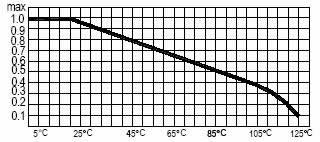
Coefficient to apply to the maximum ripple current vs temperature: See curve below
Typical Graph
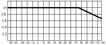
(A) Characteristics reference
For the types which can be used up to 125°C, the voltage must be derated between 85°C and +125°C according to the following curve.
(B) Leakage current change vs applied voltage: see curve below
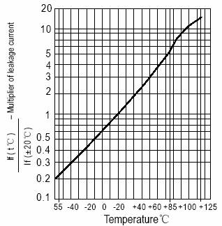
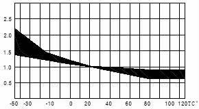
(C) Leakage current change vs temperature: see curve below
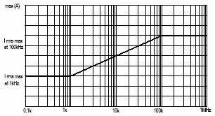
As the ESR changes in frequency, maximum ripple currents are given for two frequencies (1kHz and 100kHz). For other frequencies, apply the rule given by the curve below.
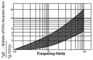
(D) Dissipation factor change vs temperature: see curve below
(E) Dissipation factor change vs Frequency: see curve below
(F) ESR change vs frequency: see table below
(G) ESR change vs frequency: see table below
As there is heating due to the ripple current, it is also necessary to derate the maximum ripple current when the room temperature is higher than 20°C.
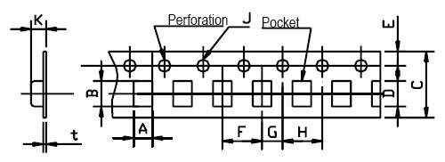
Tapping & Packing (Surface Mount)
1. TCS type
Dimensions of the carrier tape and standard parts quantity per reel
Case Size |
A±0.1 |
B±0.1 |
C±0.1 |
D±0.1 |
E±0.1 |
F±0.1 |
G±0.1 |
H±0.1 |
J+0.1 -0 |
KMAX |
t |
Quantity Per |
A |
1.9 |
3.5 |
8.0 |
3.5 |
1.75 |
4.0 |
2.0 |
4.0 |
1.5 |
2.5 |
0.2 |
2000 |
B |
3.3 |
3.9 |
8.0 |
3.5 |
1.75 |
4.0 |
2.0 |
4.0 |
1.5 |
2.5 |
0.2 |
2000 |
C |
3.7 |
6.0 |
12.0 |
5.5 |
1.75 |
8.0 |
2.0 |
4.0 |
1.5 |
3.0 |
0.3 |
500 |
D |
4.8 |
7.7 |
12.0 |
5.5 |
1.75 |
8.0 |
2.0 |
4.0 |
1.5 |
3.4 |
0.3 |
500 |
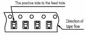
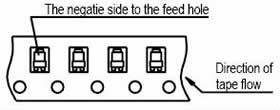
Inserting direction (Polarity orientation)
Polarity L: To be inserted with |
Polarity R: To be inserted with |
 |
 |
Reel dimensions
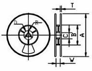 |
 |
Tape width |
8 |
12 |
A+0-3 |
Ф180 |
Ф180 |
B+1-0 |
Ф60 |
Ф60 |
C±0.2 |
Ф13 |
Ф13 |
D±0.8 |
Ф21 |
Ф21 |
E±0.5 |
2.0 |
2.0 |
W±0.3 |
9.0 |
13.0 |
t±0.4 |
1.3 |
1.3 |
R±0.4 |
10.5 |
10.5 |
2. TCD type
I. The capacity of the plastic bags depends on:
| Case Size | Cut Dimension |
Quantity Per Bag |
||
From A to D |
From E to K |
From L to N |
||
| Case Size Format 1 | Cut <7mm |
1000 |
1000 |
500 |
| Case Size Format 2 | Cut ≥14mm |
1000 |
500 |
250 |
| Case Size Format 2 | - |
1000 |
500 |
250 |
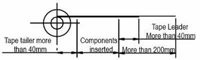
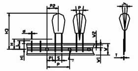
II. TAPE & AMMO PACKING (conform to : IEC286-2)
Radial Tape & Ammo Packing (conform to: IEC286-2)
Format 1 |
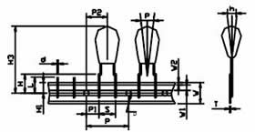
Format 2 |
 |
 |
| Item | Code |
Dimension (mm) |
|---|---|---|
| Carrier tape width | W |
18.0±1.5 |
| Hold down tape width | W1 |
6.0±0.5 |
| Feed hole diameter | W2 |
1.0 max |
| Feed hole pitch | D |
4.0±0.2 |
| Hole center to lead | P |
12.7±0.3 |
| Hole center to component | P1 |
Format 1: 5.05±0.7 |
Format 2: 3.85±0.7 |
||
| Lead wire clench height | P |
6.35±1.0 |
| Hole position | H |
16.5±0.5 |
| Base of component height | H1 |
9.0±0.5 |
| Component height | H2 |
0.8 min |
| Component height | H3 |
32.2 max |
| Component alignment | P |
0±1.3 |
h |
0±2.0 |
|
| Lead spacing | S |
'S' wires: 2.5±0.6 0.1 |
'B' wires: 2.5±0.6 0.5 |
||
| Lead diameter | d |
0.5±0.05 |
| Length of snipped lead | L |
11.0 max |
| Carrier tape thickness | T |
0.5±0.1 |
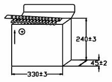
Case Code |
A~E |
F~J |
K~N |
|---|---|---|---|
QTY. (PCS/box) |
2500 |
2000 |
1000 |
Tantalum Electrolytic Capacitors Part Number System
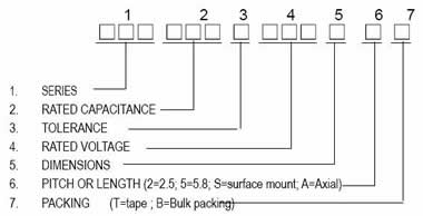
1. Series
Code |
Description |
|---|---|
TCS |
Tantalum electrolytic capacitors surface mount type |
TCD |
Tantalum electrolytic capacitors resin dipped |
TCA |
Metal case tantalum capacitors |
2. Rated Capacitance
Code |
101 |
102 |
103 |
104 |
105 |
106 |
0107 |
0108 |
|---|---|---|---|---|---|---|---|---|
PF |
100PF |
1000PF |
10000PF |
100000PF |
1000000PF |
- |
- |
- |
NF |
- |
1NF |
10NF |
100NF |
1000NF |
- |
- |
- |
µF |
- |
0.001µF |
0.01µF |
0.1µF |
1.0µF |
10µF |
100µF |
1000µF |
3. Tolerance
| Tolerance | ±10% |
±20% |
| Symbols | K |
M |
4. Rated Voltage
| Voltage | 4V |
6.3V |
10V |
16V |
20V |
25V |
35V |
40V |
50V |
63V |
100V |
125V |
| Symbols | 004 |
006 |
010 |
016 |
020 |
025 |
035 |
040 |
050 |
063 |
100 |
125 |
5. Dimensions
TCS Size |
Code |
|||
A |
B |
C |
D |
|
W±0.2 |
3.2 |
3.5 |
6.0 |
7.3 |
H±0.2 |
1.6 |
1.9 |
2.5 |
2.8 |
T±0.3 |
1.6 |
2.8 |
3.2 |
4.3 |
S±0.3 |
0.8 |
0.8 |
1.3 |
1.3 |
W2±0.1 |
1.2 |
2.2 |
2.2 |
2.4 |
TCD Size |
Code |
|||||
A |
B |
C |
D |
E |
F |
|
H |
6.0 |
7.2 |
8.0 |
9.4 |
11.5 |
12.5 |
W |
4.0 |
4.8 |
5.5 |
6.0 |
7.2 |
8.2 |
T |
3.8 |
4.6 |
5.3 |
5.8 |
7.0 |
8.0 |
TCA Size
|
Code |
|||||
A |
B |
C |
D |
E |
F |
|
DxL |
5x14 |
6x16 |
8x16 |
8x22 |
10x22 |
10x25 |
d 0.05 |
0.8 |
0.8 |
0.8 |
0.8 |
0.8 |
0.8 |