home
home contact us
 about us
OEM Service
The OEM department specializes designing and manufacturing capacitors. We supply kinds of capacitors. Welcome to OEM services, please tell your demand, and we will feedback in 24 hours. Please contact us: ctcheam@camelcom.com.my.
| A. MLCC RADIAL & AXIAL |
| B. CERAMIC DISC |
| C. SAFETY DISC (AC CAPACITOR) |
A. MLCC Radial & Axial
Class I
Temperature Compensating Capacitors have a ceramic dielectric that is formulated to provide a predicable linear capacitance change versus temperature. This predicable linear capacitance change allows to be used in critical circuit applications such as tuned circuit.
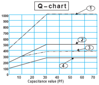
Q-chart
- NPO-N1500 initial
- Over N1500 initial
- NPO-N1500 after life
- Over N1500 after life
Electrical Specification
| Item | Specification | Testing method |
| Capacitance | To be within the spec. tolerance | Shall be measured at 25±1°C |
| Dissipation factor | C>30pf, DF:0.1% max C≤30pf, Q=400+20°C min |
1.0±0.2 Vrms and 1 MHz, 1 KHz for value above 1000 pf. |
| Insulation resistance | Cap.≤10nF: I.R≥100GΩ |
Shall be measured 60±5 sec, at rated voltage |
| Dielectric strength | To be within the 250% rated voltage | With 50mA (max) charging current |
Class II, III
The HI-K (Dielectric constant) capacitor, the maximum capacitance can be controlled in tolerance when the temperature is over 25°C. The general application in circuit where a large amount if capacitance is required but less sensitive to change with temperature variation such as “coupling”, “by pass” circuit.
Electrical Specification
Item |
Specification | Testing method |
| Capacitance | To be within the spec. tolerance | Shall be measured at 25±1°C, X7R, Y5V: 1.0±0.2V and 1KHz Z5U: 0.5V±1 and 1KHz |
| Dissipation factor | X7R: 2.5% max Z5U: 4% max Y5V: 5% max |
|
| Insulation resistance | Cap.≤10nF: I.R≥100GΩ Cap.>10nF: I.R≥100GΩ - µF |
Shall be measured 60±5 sec, at rated voltage |
| Dielectric strength | To be within the 250% rated voltage | With 50mA (max) charging current |
Reliability testing:
|
Item | Specification | Testing method |
| Humidity test | Appearance | No damage | Temperature: 40±2°C Relative humidity: 90%~95% Duration: 500+24/-0 hrs Test step:
|
| Capacitance | Capacitance change NPO: ±2% or 1.0pF X7R: ±20% Z5U, Y5V: ±30% |
||
| Dissipation factor | Dissipation factor change NPO: 0.5% max X7R, Z5U: 5% max Y5V: 7.5% max |
||
| Insulation resistance | Cap.≤10nF: I.R≥10GΩ Cap.>10nF: I.R≥100MΩ-µF |
||
| Life test | Appearance | No damage | Ambient temperature: 85±2°C Applied voltage: 200% the rated voltage Duration: 1000+48/-0hrs Charging and discharging current shall be limited to 50mA (max).Deaging at 150°C for 2hrs and recover 24hrs before measure. (NPO unnecessary) |
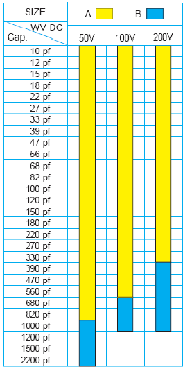
Range Chart
NPO (COG) SERIES
|
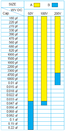
X7R SERIES
|
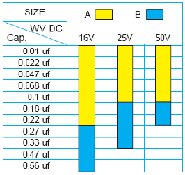
Z5U SERIES
|
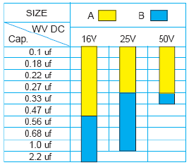
Y5V SERIES
|
Mechanical Specification
| Specification | Test Condition | |
| Marking | To be dear and legible | Marking shall be tested with Acetone. |
| Terminal strength | Tensile strength: No breakdown | Wire dia. 0.55mm, loading weight 1.0kg for 10±1sec. |
| Bending strength: No breakdown | Wire dia. 0.55mm, loading weight 0.5kg (Bend back and forth 90° twice) | |
| Solder ability | Lead wire to be soldered up to the dipped end point, with no gap in the axial direction, over ¾ of the circumferential direction. | Solder temperature: 235±5°C Dipping: 2±0.5sec Flux shall be used. |
|
 |
Dimension (Dimension
Lead Style |
Side Code |
Pitch (F)±0.5 |
Length (L) Max. |
Width (W) Max. |
Thick (T) Max. |
Seat Height (M) Max. |
Lead Length (A) |
H |
A |
5.08 |
3.81 |
3.81 |
2.54 |
2.54 |
Standard Long Lead: 25±1.0Standard Short Lead: 3±0.5 4±0.5 5±0.5 |
B |
5.08 |
5.08 |
5.08 |
3.18 |
2.54 |
||
K |
A |
2.54 |
3.81 |
3.81 |
2.54 |
3.50 |
|
B |
2.54 |
5.08 |
5.08 |
3.81 |
3.50 |
||
B |
5.08 |
5.08 |
5.08 |
3.81 |
3.50 |
||
L |
A |
2.54 |
3.81 |
3.81 |
2.54 |
1.00 |
|
B |
2.54 |
5.08 |
5.08 |
3.81 |
1.00 |
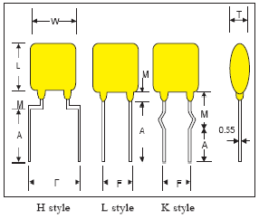 |
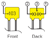
Marking principle:
|
Packing Specification
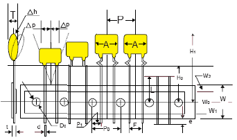
|
|
Unit:mm | Unit:inch |
| Body Dimension | A |
11.0*11.0 Max | 0.43*0.43 Ref |
| Body Thickness | T |
4.0 Max | 0.157 Ref |
| Wire Lead Dia. | d |
0.55±0.05 | #24 AWG |
| Taping Pitch | P |
12.7 Ref | 0.05 Ref |
| Feed Hole Pitch (Note:1) | P0 |
12.7±0.3 | 0.5 Ref |
| Plane Deviation | DP |
+1.0 Max | 0.0394 Ref |
| Feed Hole Off Alignment (2e) | P1 |
3.81±0.7 | 0.15 Ref (F=5.08) |
| Feed Hole Off Alignment (1e) | P2 |
5.08±0.7 | 0.30 Ref (F=2.54) |
| Lead Spacing | F F |
5.08±0.5 2.54±0.5 |
0.2 Ref 0.10 Ref |
| Body Inclination | Dn |
0±1.0 | 0±0.39 Ref |
| Carrier Tape Width | W |
18.0±1.0 | 0.709 Ref |
| Adhesive Tape Width | W0 |
13.0 Ref | 0.512 Ref |
| Feed Hole Ht Off Alignment | W1 |
9.0+0.75/-0.5 | 0.354 Ref |
| Adhesive Tape Width | W2 |
3.0 Ref | 0.118 Ref |
| Straight Lead Height (Note:2) | H |
20.0±0.5 | 0.787 Ref |
| Lead Crimp Height | H0 |
16.0 or 18.0±0.5 | 0.63 Ref |
| Top if Component Height | H1 |
32.0 Max | 1.20 Ref |
| Lead End Protrusion | e |
1.0 Max | 0.039 Ref |
| Feed Hole Diameter | D0 |
4.0±0.3 | 0.157 Ref |
| Overall Tape Thickness | t |
0.9 Max | 0.035 Ref |
| Rejected Component Cut Height | L |
10.0 Max | 0.394 Ref |
- Cumulative pitch tolerance over 20 consecutive units not to exceed ±1.0mm
- H=20.0±0.5 for lead style. L, Ho=16 or 18.0±0.5 mm for lead style K.H
- Dimensions meet requirement defined in EIA RS468
Package Quantity
 |
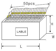
Box Size:330*250*50mm (W*L*H) |
NPO (COG) SERIES |
X7R SERIES
|
Z5U SERIES
|
Y5V SERIES
|
Mechanical Specification
|
Specification | Test Condition |
| Marking | To be clear and legible | Marking shall be test with Acetone |
| Terminal Strength | Pull force ≥ 2lb | Pull both lead ends till body broken |
| Solder Ability | Lead wire to be soldered up to the dipped end point, with no gap in the axial direction, over ¾ of the circumferential direction | Solder temperature: 235±5°C Dipping: 2±0.5sec Flux shall be used. |
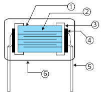
Construction
|
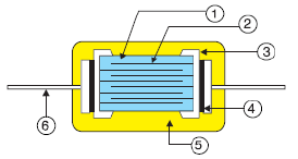 |
Marking Principle & Dimension
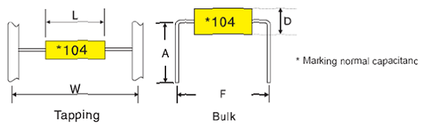
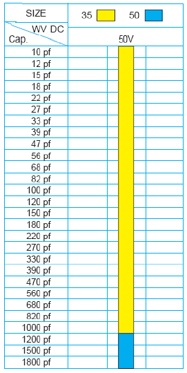
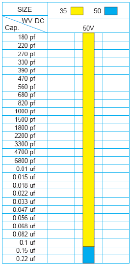
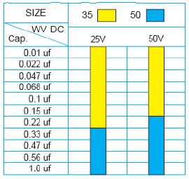
Size |
T (max) |
D (max) |
Tapping |
Bulk |
|
W (mm) |
F |
A |
|||
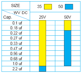
35 |
3.5 |
2.5 |
26 |
5 |
5 -> 10 |
50 |
5.0 |
3.0 |
52 |
NA |
|
Tapping Specification
|
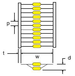 |
Packing Specification
|
 |
Package Quantity
| Size | 35 |
50 |
| Ammo | 5000 pcs |
5000 pcs |
| BULK | 1000/PE bag |
|
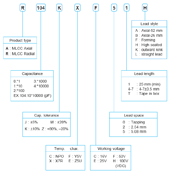
Part Number System