 home
home contact us
 about us
OEM Service
The OEM department specializes designing and manufacturing capacitors. We supply kinds of capacitors. Welcome to OEM services, please tell your demand, and we will feedback in 24 hours. Please contact us: ctcheam@camelcom.com.my.
| A. MLCC RADIAL & AXIAL |
| B. CERAMIC DISC |
| C. SAFETY DISC (AC CAPACITOR) |
B. Ceramic Disc
Temperature Compensating (TC) Capacitors 50 (160) ~ 6000WVDC
EIA RS 198 (Class I) |
Features: |
Specifications:
| Operating Temp. Range | -25°C to +85°C | |||||||||||||
| Capacitance | Range | 0.5 to 1000PF measured at 1MHz±10%, 1Vrms, 25°C | ||||||||||||
| Tolerance | ±0.25PF (C), ±0.5PF (D), ±5% (J), ±10% (K) | |||||||||||||
| Test Voltage | <1000VDC: 3 times of Working Voltage for 1~5 seconds | |||||||||||||
| ≥1000VDC: 2 times of Working Voltage for 1~5 seconds | ||||||||||||||
| Quality Factor (Q.F.) | NPO~N750, SL | C<30PF | Q≥400+20xC | |||||||||||
| C≥30PF | Q≥1000 | |||||||||||||
| N1000, N1500 | C<30PF | Q≥200+10xC | ||||||||||||
| C≥30PF | Q≥500 | |||||||||||||
| Insulation Resistance (I.R.) | 10000MΩ min. at working voltage for 1 minute | |||||||||||||
| Temperature Characteristic -25°C - +85°C (Fig.3) |
Cap. Change PPM/°C |
NPO ±60 |
N150 ±60 |
N220 ±60 |
N330 ±60 |
N470 ±60 |
N750 ±60 |
N1000 ±250 |
N1500 ±250 |
+350~1000 | ||||
| EIA RS 198 | C0H | P2H | R2H | S2H | T2H | U2J | V2K | W2K | S2L | |||||
| JIS C 6423 | CH | PH | RH | SH | TH | UJ | VK | WK | SL | |||||
| GB 5966-86 | C | P | R | S | T | U | Q | V | SL | |||||
| Effect of Soldering | Cap. change within: ±2.5% or ±0.25PF. To be measured after 4~24 hours (Solder Temp.: 270±5°C, Dipping duration: 3±0.5 sec.) |
|||||||||||||
| Life Test | Cap. change : within ±3% or ±3PF. Q.F. : Under 10PF, Q≥200+10C : 10PF~30PF, Q≥275+5/2C : Over 30PF, Q≥350 I.R. : >1000MΩ |
Test condition and method:
|
||||||||||||
| Solderability | It does not remain unsoldered area over ¼ of the circumference of the lead. (Solder Temp.: 235±5°C, Dipping duration: 2±0.5 sec.) |
|||||||||||||
Fig.3
TEMPERATURE CHARACTERISTICS

High Dielectric Constant (Hi-K) Capacitors 50(160)~6000WVDC
EIA RS 198 (Class II) |
Features: |
Specification:
| Operating Temp. Range | +10°C to +85°C for ZE, ZF | -25°C to +85°C for YA, YB | |||||
| Capacitance | Range | 100PF to 0.1µF measured at 1KHz±10%, 1Vrms, 25°C | |||||
| Tolerance | ±5% (J) for YA, ±10% (K) for YA, YB, ±20% (M) for YB, ZE, +80% -20% (Z) for ZE, ZF | ||||||
| Test Voltage | <1000VDC: 2.5 times of Working Voltage for 1-5 seconds | ||||||
| ≥1000VDC: 2 times of Working Voltage for 1-5 seconds | |||||||
| Dissipation Factor (D.F.) | 2.5% Max for YA, YB, ZE at 1KHz, 1Vrms, 25°C | ||||||
| 5% Max for ZF at 1KHz, 1Vrms, 25°C | |||||||
| Insulation Resistance (I.R.) | 10000MΩ min at working voltage for 1 minute | ||||||
| Temperature Characteristic -25°C ~ +85°C (Fig.4) |
Cap. change within | ±5% | ±10% | ±20/-55% | +30/-80% | ||
| EIA RS 198 | Y5E | Y5P | Z5U | Z5V | |||
| JIS C 6422 | YA | YB | ZE | ZF | |||
| GB 5968-86 | - | ZB4 | ZE4 | ZF4 | |||
| Effect of Soldering | Cap. change within: ±3.5% (YA), ±15% (ZE), ±20% (ZF) To be measured after 4-24hrs (Solder Temp.: 270±5°C, Dipping duration: 3±0.5sec) | ||||||
| Life Test | Cap. change within ±5% (YA), ±10% (YB), ±20% (ZE), ±30% (ZF) D.F.: 5% Max for YA, YB, ZE, 7.5% Max for ZF I.R. : >1000MΩ |
Test Condition and Method:
|
|||||
| Solderability | It does not remain unsoldered area over ¼ of the circumference of the lead. (Solder Temp.: 235±5°C, Dipping duration: 2±0.5sec.) |
||||||
Fig.4

Semi-Conductive (S.C.) Capacitors (Surface Layer Type)
12(16) ~ 50(100) WVDC
EIA RS 198 (Class III) |
Features: |
Specifications:
| Operating Temp. Range | -25°C to +85°C | |||||
| Capacitance | Range | 0.0027µF to 0.47µF measured at 1KHz±10%, 0.1Vrms, 25°C | ||||
| Tolerance | ±10% (K) for YB, ±20% (M) for YB, YE, +80% -20% (Z) for YE, YF | |||||
| Test Voltage | 2.5 times of Working Voltage for 1-5 seconds | |||||
| Dissipation Factor (D.F.) | 16V <7%; 25V-50V <5% at 1KHz±10%, 0.1Vrms, 25°C | |||||
| Insulation Resistance (I.R.) | 16V >100MΩ; 25V-50V >1000MΩ at working voltage for 1 minute | |||||
| Temperature Characteristic -25°C ~ +85°C (Fig.5) |
Cap. change within | ±10% | +20/-55% | +30/-80% | ||
| EIA RS 198 | Y5P | Y5U | Y5V | |||
| JIS C 6422 | YB | YE | YF | |||
| Effect of Soldering | Cap. change within: ±5% (YB), ±15% (YE), ±20% (YF) To be measured after 4-24hrs (Solder Temp.: 270±5°C, Dipping duration: 3±0.5sec) | |||||
| Life Test | Cap. change within ±10% (YB), ±20% (YE), ±30% (ZF) D.F.: 16V<10%, 25V-50V <7.5% I.R. : 16V>50MΩ, 25V-50V >500MΩ |
Test Condition and Method:
|
||||
| Solderability | It does not remain unsoldered area over ¼ of the circumference of the lead. (Solder Temp.: 235±5°C, Dipping duration: 2±0.5sec.) |
|||||
Fig.5

Range Chart (Capacitance in pF)
CLASS I / TYPE I / CC1
| W.V.DC | T.C. | ||||||
| CH NPO |
PH N150 |
RH R220 |
TH N470 |
UJ N750 |
SL +350~-100 |
Dimension Max (mm) |
|
| 50V/100V | 0.5-47 | 1-33 | 1-50 | 1-200 | 5.5 | ||
| 50-82 | 34-56 | 51-82 | 200-220 | 6.5 | |||
| 100-120 | 60-82 | 85-120 | 240-330 | 7.5 | |||
| 130-180 | 85-110 | 130-180 | 340-470 | 8.5 | |||
| 200-220 | 120-150 | 200-220 | 500-680 | 9.5 | |||
| 230-270 | 160-220 | 230-270 | 820-1000 | 10.5 | |||
| 280-330 | - | - | - | 11.5 | |||
| 340-390 | - | - | - | 12.5 | |||
| 470 | - | - | - | 14.5 | |||
CLASS II / TYPE II / CT1
| W.V.DC | T.C. | |||
| B ±10% |
E +20~-55% |
F +30~-80% |
Dimension Max (mm) |
|
| 50V/100V | 100-2200 | 1000-5600 | 1000-10000 | 5.5 |
| 2700-3300 | 6800-10000 | 10000 | 6.5 | |
| 3900-4700 | 12000 | 15000, 18000 | 7.5 | |
| 5600-6800 | 15000 | 20000, 220000 | 8.5 | |
| 8200-10000 | 18000-22000 | 30000, 330000 | 9.5 | |
| - | - | 390000, 50000 | 10.5 | |
CLASS III / TYPE III / S.C.
| W.V.DC | T.C. | |||
| YB ±10% |
YE +20~-55% |
YF +30~-80% |
Dimension Max (mm) |
|
| 16V | 3300-10000 | 3300-22000 | - | 5.5 |
| 15000-22000 | 30000-50000 | 68000-100000 | 6.5 | |
| 22000-50000 | 68000-100000 | 150000-180000 | 7.5 | |
| 68000-100000 | - | 200000-220000 | 9.5 | |
| - | 220000 | 330000-470000 | 10.5 | |
| 25V | 3300-10000 | 3300-22000 | 10000-47000 | 5.5 |
| 15000-22000 | 30000-50000 | 68000-100000 | 6.5 | |
| 22000-47000 | 68000-100000 | 150000-180000 | 7.5 | |
| - | - | 200000-220000 | 10.5 | |
| 50V | 3300-10000 | 3300-22000 | 10000-47000 | 5.5 |
| 15000-22000 | 30000-40000 | 680000 | 6.5 | |
| 22000-33000 | 47000-50000 | 100000 | 7.5 | |
| 47000 | 68000-100000 | - | 8.5 | |
| - | - | 220000 | 10.5 | |
Range Chart (Capacitance in pF)
| W.V.DC | T.C. | |||||
| CH NPO |
SL +350~-1000 |
B ±10% |
E +20~-55% |
F +30~-80% |
Dimension Max (mm) |
|
| 500V | 0.5-27 | 15-68 | 100-470 | 1000-1500 | 1000-3300 | 5.5 |
| 30-47 | 82-100 | 560-1000 | 2000-3300 | 1700-5000 | 6.5 | |
| 56-68 | 120-180 | 1500, 1800 | 3900-5000 | 5600-6800 | 7.5 | |
| 82-100 | 200-270 | 2000, 2200 | 5600, 6800 | 10000 | 8.5 | |
| - | 300-330 | 2700, 3300 | 8200 | - | 9.5 | |
| - | 340-390 | 3900, 4700 | 10000 | - | 10.5 | |
| - | - | 5600, 6800 | 15000 | 20000, 22000 | 12.5 | |
| - | - | 8200, 10000 | 20000, 22000 | 47000 | 14.5 | |
| - | - | - | - | 100000 | 20.5 | |
| 1KV | 1-22 | 1-68 | 100-500 | 1000 | 1000-3300 | 5.5 |
| - | - | 560-1000 | 1500-2200 | 4700-5000 | 6.5 | |
| 25-39 | 75-110 | 1200-1500 | 2700 | 5600 | 7.5 | |
| - | - | 1800-2000 | 3000-3900 | 6800 | 8.5 | |
| 47, 50 | 120-200 | 2200 | 4700-5600 | - | 9.5 | |
| 51-100 | 220-300 | 2700, 3000 | 6800-8200 | 10000 | 10.5 | |
| 100-120 | 330-390 | 3300, 4700 | 10000 | - | 12.5 | |
| 150 | 470-560 | 5600, 6800 | 15000 | 22000 | 14.5 | |
| 220 | 620-750 | 8200, 10000 | - | - | 18.5 | |
| 330 | 820-1000 | - | - | 47000 | 20.5 | |
| 2KV | 1-22 | 1-47 | 100-150 | 1000, 1200 | 1000, 1200 | 7.5 |
| - | 68-100 | 180-470 | - | 1500, 1800 | 8.5 | |
| - | - | 500-680 | 1500, 1800 | 2000-2700 | 9.5 | |
| - | - | 820, 1000 | 2000-2700 | 3000-3900 | 10.5 | |
| - | - | 1200-2200 | 3000-3900 | 4700-5600 | 11.5 | |
| - | - | 2700, 3000 | 4700-5000 | 6800-10000 | 13.5 | |
| - | - | 2700, 3000 | 5600 | - | 15.5 | |
| - | - | 3300 | 6800 | - | 16.5 | |
| - | - | 3900-5000 | 8200, 10000 | 15000 | 17.5 | |
| - | - | 5600, 6800 | - | - | 20.5 | |
| - | - | 8200, 10000 | - | 22000 | 23.5 | |
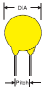
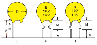
Lead Pitch V.S. Body Size
“ê” Standard pitch for w.v. 2kv & above “O” Available for customers’ requirement |
 |
|||||||||||||||||||||||||||||||||||||||||||||||||||||
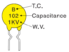
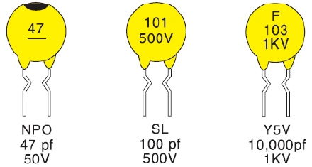
Marking Principle
Line 1: Temperature characteristic
| Item | NPO |
N220 |
N750 |
SL |
Y5P |
Y5U (Z5U) |
Y5V (Z5V) |
| Code | CH |
RH |
UJ |
S |
B |
E |
F |
| Mark | Black dot |
Yellow dot |
Violet dot |
None |
B |
E |
F |
Line 2: Capacitance
Mark a bar (---) for 50V-100V otherwise mark the exact volt |
 |
EX:
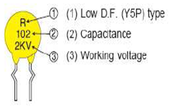
Low D.F. Type
- Low D.F. performance V.S. high temperature
- Low power loss in linear circuit “power supply” “monitor” “T.V. set”
Range Chart
T.C. |
D.F | Capacitance | Pitch | Dia. (mm) |
| Y5P (2KV) |
0.5% (max) |
100-390pF | 5, 7.5 | 7 |
| 470-680pF | 5, 7.5 | 9 | ||
| 820-1000pF | 5, 7.5 | 11 | ||
| 1200pF | 7.5, 10 | 12 | ||
| 2700pF | 7.5, 10 | 15 |
Electrical Specification
|
Specification | Test Condition |
| Capacitance | To be within the spec tolerance | To be measured at 25°C±1°C at 1±0.2Vrms 1KHz |
| Dissipation factor | D.F ≤0.5% | |
| Insulation resistance | I.R. ≥10GΩ | To be measured at 500VDC |
| Dielectric strength | With standing 200% W.V. | 200% working voltage applied |
| Temperature characteristic and D.F. curves | 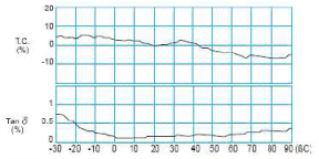 |
Marking Principle
|
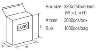
Package Quantity
|
Packing Specification
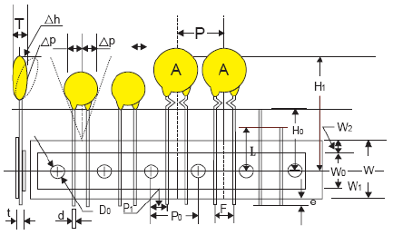
| Item | Unit: mm | Unit: inch | |
| Body Dimension | A |
11.0*11.0 Max | 0.43*0.43 Ref |
| Body Thickness | T |
4.0 Max | 0.157 Ref |
| Wire Lead Dia. | d |
0.60±0.05 | #24 AWG |
| Taping Pitch | P |
12.7 Ref | 0.05 Ref |
| Feed Hole Pitch (Note: 1) | P0 |
12.7±0.3 | 0.5 Ref |
| Plane Deviation | DP |
+1.0 Max | 0.0394 Ref |
| Feed Hole Off Alignment (2e) | P1 |
3.81±0.7 | 0.15 Ref (F=5.08) |
| Feed Hole Off Alignment (1e) | P2 |
5.08±0.7 | 0.20 Ref (F=2.54) |
| Lead Spacing | F |
5.08±0.5 | 0.2 Ref |
F |
2.54±0.5 | 0.10 Ref | |
| Body Inclination | Dh |
0±1.0 | 0±0.39 Ref |
| Carrier Tape Width | W |
18.0±1.0/-0 | 0.709 Ref |
| Adhesive Tape Width | W0 |
13.0 Ref | 0.512 Ref |
| Feed Hole Ht Off Alignment | W1 |
9.0 +0.75/-0.5 | 0.354 Ref |
| Adhesive Tape Width | W2 |
3.0 Ref | 0.118 Ref |
| Straight Lead Height (Note: 2) | H |
20.0±0.5 | 0.787 Ref |
| Lead Crimp Height | H0 |
16.0 or 18.0±0.5 | 0.63 Ref |
| Top of Component Height | H1 |
32.0 Max | 1.20 Ref |
| Lead End Protrusion | e |
1.0 Max | 0.039 Ref |
| Feed Hole Diameter | D0 |
4.0±0.3 | 0.157 Ref |
| Overall Tape Thickness | t |
0.9 Max | 0.035 Ref |
| Rejected Component Cut Height | L |
10.0 Max | 0.394 Ref |
Note:
- Cumulative pitch tolerance over 20 consecutive units not to exceed ±1.0mm
- H=20.0±0.5 for lead style. L, H0=16 or 18.0±0.5mm for lead style K, I
- Dimensions meet requirement defined in EIA RS468
Part Number System
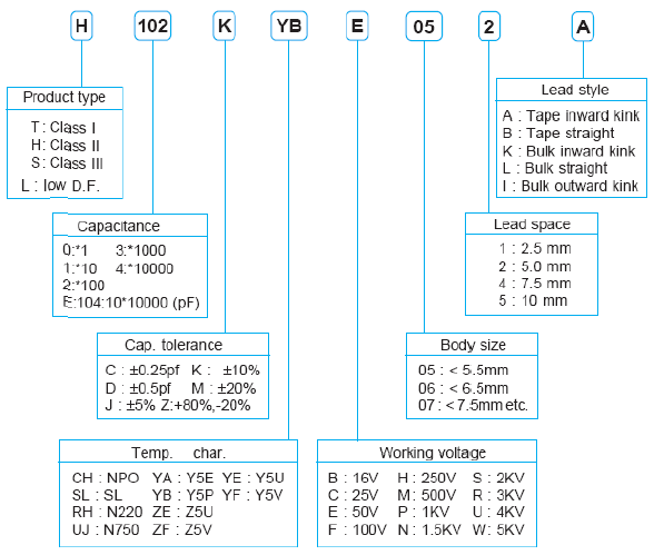
Lead Style
|
 |